 Quanzhou Ausenist Technology Co., Ltd
 22kW Irrigation Pump VFD Solution with Pressure Control
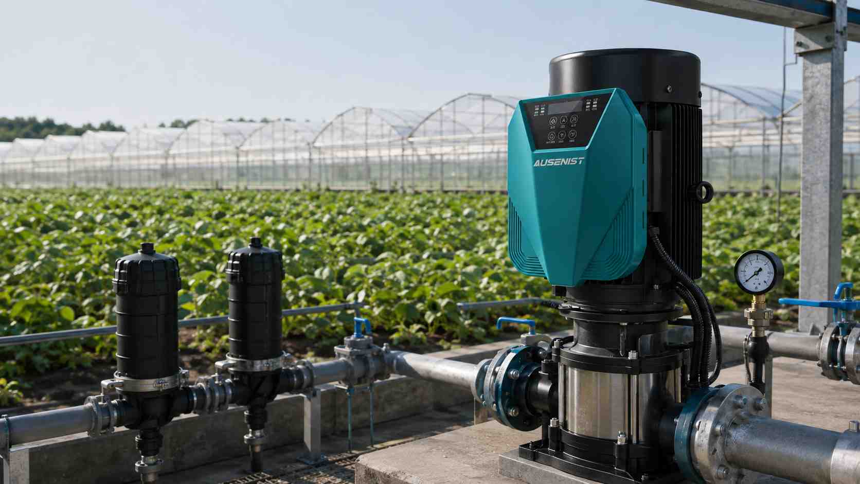
Engineering reference rendering; it is not a customer-site photograph.
A 22kW irrigation pump VFD should maintain the pressure required by the active irrigation zone without forcing the pump to run at full speed continuously. Selection begins with motor rated current and the pump curve. Control design must also account for changing valve zones, water-source level, filtration loss and the minimum flow permitted by the pump.
Reference Design at a Glance
| Item | Reference Requirement |
|---|---|
| Reference market | Chile |
| Pump | 22kW centrifugal irrigation pump |
| Motor | 380V three-phase, 50Hz |
| Control | Constant pressure across multiple irrigation zones |
| Feedback | 4–20mA pressure transmitter |
| Suggested series | AUSENIST YS620 or YS820, 380V class |
| Protection focus | Dry running, low pressure and pipe-failure response |
What Information Is Required?
- Motor nameplate and pump performance curve.
- Available voltage, phase, frequency and generator details if used.
- Required pressure and flow for each irrigation zone.
- Static lift, pipe length, filter loss and valve arrangement.
- Water-source level variation and dry-run detection method.
- Ambient temperature, dust exposure and installation enclosure.
- Remote start, fertigation or PLC/BMS communication needs.
Selection Example
For a 22kW, 380V motor, choose the AUSENIST drive current class only after comparing its continuous output current with the motor nameplate current. Install the pressure transmitter at a point that represents the controlled network—not directly beside a turbulent discharge fitting.
Begin PID tuning with moderate response. Open the smallest zone and the largest zone during commissioning, then confirm that pressure remains stable without driving the pump below its safe hydraulic range.
Recommended Basic Configuration
| Setting | Initial Direction |
|---|---|
| Pressure setpoint | Use the highest verified zone requirement with control margin |
| Minimum frequency | Protect pump cooling and minimum useful flow |
| Acceleration/deceleration | Smooth enough to limit pipe pressure shock |
| Sleep/wake | Test with the smallest active zone and zero-demand condition |
| Dry-run logic | Combine source condition with current/pressure evidence where possible |
| Restart attempts | Limit and delay to protect the borehole or reservoir supply |
Why This Configuration?
Pressure feedback lets the VFD follow real network demand as valves open and close. A properly chosen sensor location and stable PID response are more valuable than aggressive tuning. The VFD cannot correct an undersized pipe, blocked filter or pump operating outside its curve.
Expected Result and Acceptance Checks
Expected operation includes gradual pump starting, controlled pressure during zone changes and protective stopping when the water source is unavailable. Verify motor current, minimum and maximum zone pressure, filter-clean versus filter-dirty behavior, sensor failure response and generator stability if applicable.
Common Mistakes
- Choosing the drive by 22kW without checking rated current.
- Placing the pressure sensor where turbulence produces unstable feedback.
- Setting one pressure target without checking all irrigation zones.
- Allowing unlimited automatic restarts after dry-run trips.
- Assuming lower speed always saves energy even when the pump is outside its efficient range.
AUSENIST Solution
AUSENIST can select the pump-drive current class, scale the pressure feedback, prepare irrigation-oriented protection parameters and support OEM enclosures or branding. Systems with highly variable sources, solar inputs or mixed pump sizes require project-specific review.
FAQ
Can one pressure setpoint serve every irrigation zone?
Sometimes, but zones with very different elevation or flow may need separate setpoints or external control logic.
Can the VFD run from a generator?
Yes in suitable designs, but generator capacity, voltage regulation and acceleration settings must be checked.
Where should the pressure transmitter be installed?
At a stable point that represents network pressure and is accessible for isolation, testing and replacement.
Send us the motor nameplate, pump curve, zone pressure/flow table, supply and water-source data. We can prepare a VFD selection and basic irrigation control configuration.