 Quanzhou Ausenist Technology Co., Ltd


About UsMore
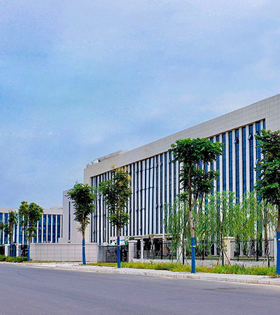
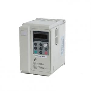
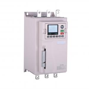
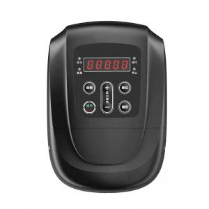
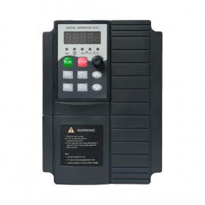
Ausenist Technology Co., Ltd is a distinguished international enterprise specializing in the research, development, production, sales, and service of inverters, holding exclusive intellectual property rights in China. Our primary focus revolves around catering to the needs of industrial equipment manufacturers, delivering not only practical products and convenient services but also bespoke solutions tailored to specific industries. Our core expertise lies in AC drive automatic control technology.
With a commitment to continuous improvement and systematic innovation, Ausenist has positioned itself as a leader in the field. We take pride in our mastery of vector control technology and torque control technology, aligning seamlessly with international advanced standards. Through relentless technical innovation and global technology collaborations, we have achieved a perfect blend of design and production capabilities, significantly enhancing product reliability and adaptability to various environments.
At the heart of our success is a team of professional R&D engineers, encompassing both hardware and software experts. Supported by a management team with extensive international experience, Ausenist is well-equipped to tackle a diverse array of technical c...

News
-
-
A-51 - Industrial Instrumentation Parts
A-51 and other industrial components, original par

Our Partners












Faqs

Why Does a Water Pump Run Backwards After VFD Installation?
Why Does a Water Pump Run Backwards After VFD Installation?
A water pump may run backwards after VFD installation because the motor phase sequence at the VFD output is reversed or the run direction command is set incorrectly. Reverse rotation can reduce flow, damage some pumps and create confusing pressure readings.
Recommended Configuration
| Item | Reference Selection |
|---|---|
| Pump | Centrifugal, booster, borehole or transfer pump |
| Motor | Three-phase pump motor |
| Direction | Rotation checked before full-load operation |
| Wiring | Output phase sequence corrected only when safe and powered down |
| Control | Forward/reverse command reviewed in parameters and terminals |
| VFD | AUSENIST pump VFD configured for correct pump direction |
What Must Be
Why Does a Water Pump Run Backwards After VFD Installation?
Why Does a Water Pump Run Backwards After VFD Installation?
A water pump may run backwards after VFD installation because the motor phase sequence at the VFD output is reversed or the run direction command is set incorrectly. Reverse rotation can reduce flow, damage some pumps and create confusing pressure readings.
Recommended Configuration
| Item | Reference Selection |
|---|---|
| Pump | Centrifugal, booster, borehole or transfer pump |
| Motor | Three-phase pump motor |
| Direction | Rotation checked before full-load operation |
| Wiring | Output phase sequence corrected only when safe and powered down |
| Control | Forward/reverse command reviewed in parameters and terminals |
| VFD | AUSENIST pump VFD configured for correct pump direction |
What Must Be
Should Submersible Pump Motor Insulation Be Checked Before Using a VFD?
Should Submersible Pump Motor Insulation Be Checked Before Using a VFD?
Yes. Submersible pump motor insulation should be checked before connecting a VFD, especially for old borehole pumps, wet environments and long motor cables. Poor insulation can cause leakage current, nuisance trips or motor failure.
Recommended Configuration
| Item | Reference Selection |
|---|---|
| Pump | Submersible, borehole or deep well pump |
| Motor | Three-phase submersible motor suitable for VFD operation |
| Check | Insulation, cable condition and grounding reviewed |
| Cable | Length and insulation quality confirmed |
| Protection | Ground fault, overload and dry-run protection considered |
| VFD | AUSENIST pump VFD selected by motor current and installation condition |
What Mu
Star or Delta Connection for a Pump Motor with a VFD?
Star or Delta Connection for a Pump Motor with a VFD?
A pump motor should be connected in the star or delta arrangement that matches the VFD output voltage and motor nameplate. Do not choose the connection by habit; choose it from the motor voltage markings and the actual drive voltage class.
Recommended Configuration
| Item | Reference Selection |
|---|---|
| Motor | Three-phase pump motor with clear nameplate voltage |
| Connection | Star or delta according to nameplate and VFD output voltage |
| Input | Site supply matched to selected VFD |
| Output | VFD output voltage matched to motor winding requirement |
| Protection | Motor current, overload and phase-loss checks |
| VFD | AUSENIST pump VFD selected by motor rated current |
What Must Be Confirmed?
How to Wire Remote Start Stop Control for a Pump VFD?
How to Wire Remote Start Stop Control for a Pump VFD?
Remote start-stop control for a pump VFD is normally done through digital input terminals configured for run command, stop command or forward operation. The exact wiring depends on the selected VFD model, control mode and whether the signal comes from a switch, float, relay or PLC.
Recommended Configuration
| Item | Reference Selection | ||||||||||||||||||||||||||||
|---|---|---|---|---|---|---|---|---|---|---|---|---|---|---|---|---|---|---|---|---|---|---|---|---|---|---|---|---|---|
| Command | Digital input terminal for remote run/stop | ||||||||||||||||||||||||||||
| Signal Source | Switch, float switch, pressure switch, relay or PLC contact | ||||||||||||||||||||||||||||
| Speed Reference | Keypad, analog input, PID setpoint or external command | ||||||||||||||||||||||||||||
| Safety | Emergency stop and protection circuit as required | ||||||||||||||||||||||||||||
| Feedback | Run, fault or ready relay output if needed | ||||||||||||||||||||||||||||
| VFD | AUSENIST pump VFD configured for terminal control
Why Does a Pump VFD Show Undervoltage or Phase Loss?Why Does a Pump VFD Show Undervoltage or Phase Loss?A pump VFD shows undervoltage or phase loss when the input supply is unstable, one phase is missing, voltage drops during acceleration, wiring is loose or the power source cannot support the pump load. The fault should be checked under running conditions, not only at no load. Recommended Configuration
What Must |