 Quanzhou Ausenist Technology Co., Ltd
 How to Control Cooling-Water Differential Pressure with an 18.5kW VFD
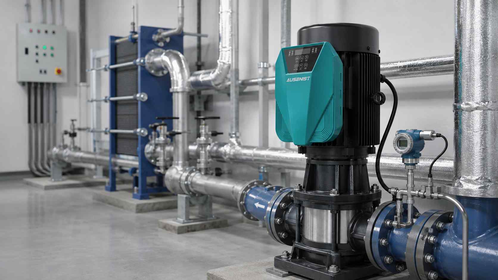
Engineering reference rendering; it is not a photograph of an operating customer plant.
For an 18.5kW cooling-water circulation pump, a differential-pressure transmitter can provide the VFD with direct feedback from the distribution loop. The drive adjusts speed to maintain the required pressure difference while a verified minimum-frequency or bypass strategy protects minimum cooling flow. Motor current and continuous-duty conditions still determine the VFD size.
Reference Design at a Glance
| Item | Reference Requirement |
|---|---|
| Reference market | Saudi Arabia |
| Pump | 18.5kW centrifugal circulation pump |
| Motor | 400V three-phase, 50Hz |
| Duty | Long-duration industrial operation |
| Control | Differential pressure or PLC speed command |
| Suggested series | AUSENIST YS620 or YS820, 400V-class project configuration |
| Environment | Hot plant room; ventilation review required |
What Information Is Required?
- Motor nameplate and measured full-flow current if available.
- Pump curve, system curve and required minimum cooling flow.
- Supply voltage/frequency and plant fault level information where required.
- Control signal source and feedback range.
- Maximum ambient temperature and enclosure ventilation.
- Motor-cable length, EMC requirements and communication interface.
- Operating hours, standby arrangement and restart philosophy.
Selection Example
For an 18.5kW, 400V motor, compare the motor rated current with the selected VFD’s continuous output current. Apply any temperature or enclosure derating. If the plant room is hot and the current margin is small, select a higher current frame or improve cooling rather than accepting recurring thermal trips.
For a variable-flow cooling loop, differential pressure across the distribution circuit often provides a useful feedback signal. A PLC speed reference may be better where the process controller already calculates demand.
Recommended Basic Configuration
| Setting | Initial Direction |
|---|---|
| Motor values | Enter exact nameplate voltage, current, frequency and speed |
| Minimum frequency | Protect minimum cooling flow and equipment limits |
| Acceleration/deceleration | Coordinate with valves and system volume |
| Control source | Select PLC, terminal or PID feedback explicitly |
| Signal-loss action | Define safe fixed speed, stop or alarm response |
| Restart | Coordinate with plant sequencing after a power loss |
Why This Configuration?
Continuous-duty selection provides thermal margin, while process feedback allows speed to follow actual cooling demand. The minimum-speed limit protects heat exchangers and equipment that require continuous flow. Signal-loss behavior must be decided before commissioning because an automatic stop may be unsafe for some processes.
Expected Result and Acceptance Checks
Expected behavior is smooth starting, stable control and adequate cooling flow throughout the process range. Record motor current, differential pressure, temperatures, low-demand stability, maximum ambient condition and signal-loss response. Energy performance should be calculated from measured power and operating hours, not a fixed promotional percentage.
Common Mistakes
- Matching only 18.5kW and ignoring current or high ambient temperature.
- Reducing speed below the minimum process flow.
- Choosing a feedback point that does not represent the critical circuit.
- Leaving sensor-loss behavior at an unsuitable default.
- Installing the VFD beside a heat source without a thermal review.
AUSENIST Solution
AUSENIST can select the current class, support PID or PLC integration, prepare signal scaling and review communication, cable and high-temperature requirements. Specialized harmonic, EMC or redundancy specifications must be included in the project data before quotation.
FAQ
Is PID always required for a cooling pump?
No. A PLC or building controller can provide the speed reference when it already manages the process.
Can the pump stop during low cooling demand?
Only if the process design permits zero flow. Many systems require a verified minimum circulation rate.
How should energy savings be estimated?
Use measured baseline power, new power at representative speeds and actual annual operating hours.
Send us the motor nameplate, pump/system curves, control signal, ambient temperature and operating schedule. We can recommend the VFD and control configuration.