 Quanzhou Ausenist Technology Co., Ltd
 15kW Booster Pump VFD with a 0–10 Bar Pressure Sensor: Peru Reference Design
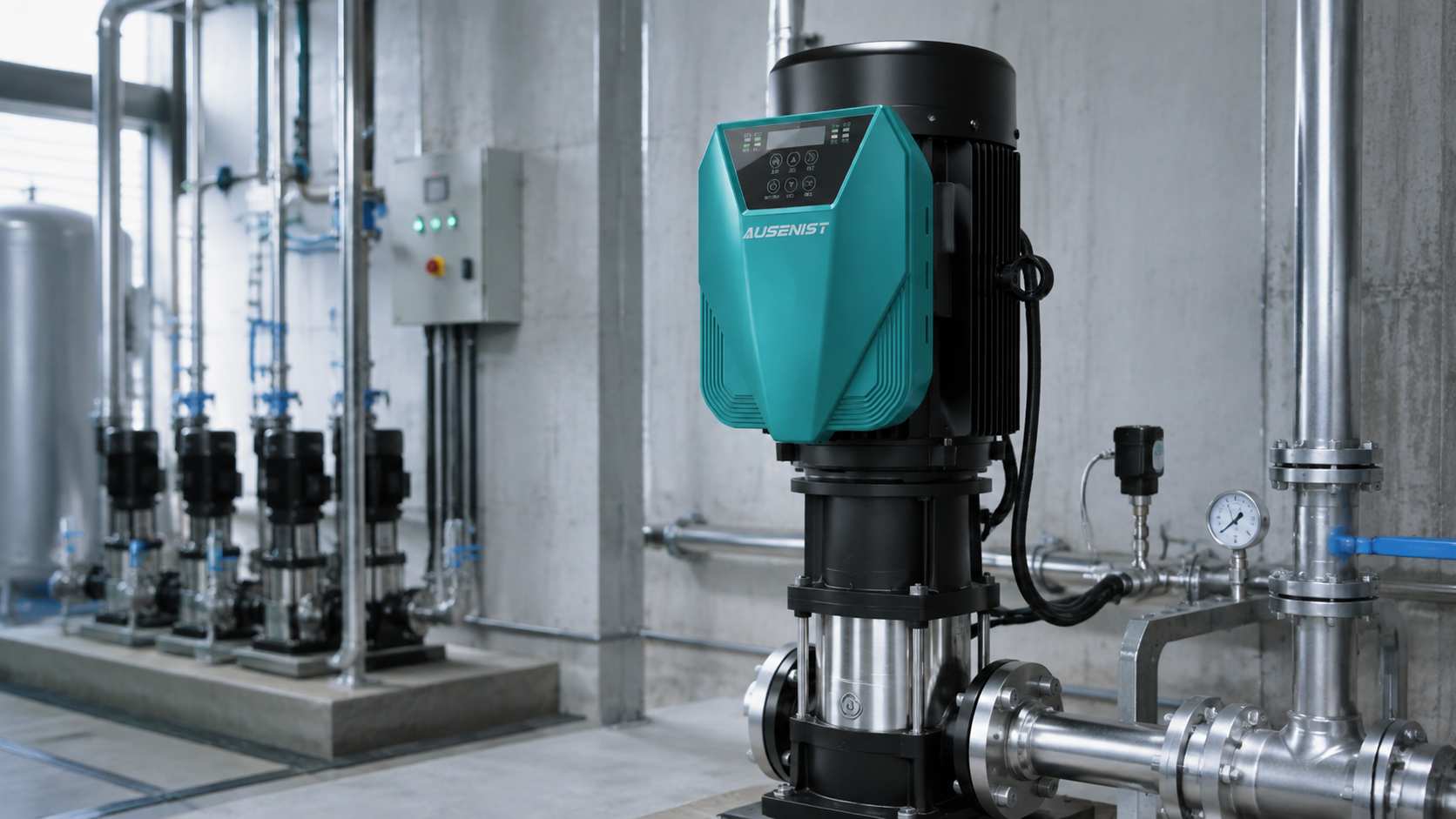
Engineering reference rendering for solution discussion; it is not a customer-site photograph.
For a 15kW constant-pressure booster pump, the VFD should be selected by motor rated current—not by 15kW alone. In this Peru reference design, a 380V three-phase, 60Hz motor is paired with an AUSENIST 380V-class pump VFD and a 0–10 bar, 4–20mA pressure transmitter. A 4.0 bar setpoint is used only as a commissioning example; the real target must come from the hydraulic design.
Reference Design at a Glance
| Item | Reference Requirement |
|---|---|
| Market | Peru |
| Pump | 15kW vertical multistage booster pump |
| Motor | 380V three-phase, 60Hz induction motor |
| Supply | 380V three-phase, 60Hz |
| Control target | 4.0 bar example setpoint |
| Feedback | 0–10 bar, 4–20mA pressure transmitter |
| Suggested series | AUSENIST YS620 or YS820, 380V class |
This is a selectable engineering configuration that AUSENIST can prepare for a comparable project. It does not claim a measured result from a named installation.
What Information Is Required?
Before confirming the model, provide:
- A clear motor nameplate showing voltage, current, power, frequency, speed and motor type.
- Available supply voltage, phase and frequency at the site.
- Pump curve, target pressure, expected flow range and static head.
- Quantity of pumps and whether lead/lag or standby logic is required.
- Pressure transmitter range and signal type.
- Ambient temperature, installation method and motor-cable length.
Selection and Basic Configuration
The VFD output current must be equal to or greater than the motor nameplate current after site conditions are considered. A 15kW label on both devices is not sufficient if the motor current is unusually high or the installation requires derating.
Recommended starting configuration:
| Setting | Initial Direction |
|---|---|
| Motor data | Enter the complete nameplate values |
| Maximum frequency | Match the motor and pump permitted speed |
| Pressure setpoint | 4.0 bar example; replace with the approved design value |
| PID feedback scale | 4mA = 0 bar; 20mA = 10 bar |
| Acceleration/deceleration | Use gradual ramps to reduce hydraulic shock |
| Sleep/wake | Enable only after the no-flow behavior is tested |
| Dry-run protection | Commission against the actual water-source condition |
Why This Configuration?
The pressure transmitter gives the VFD continuous feedback. When demand rises, pressure falls and the drive increases pump speed. When demand falls, the drive reduces speed. Correct signal scaling is essential: if the VFD is programmed for a 0–16 bar sensor while a 0–10 bar sensor is installed, the displayed pressure and PID response will be wrong.
The 60Hz motor data must be entered correctly. A technician should also verify that the pump remains inside its permitted operating range at minimum and maximum speed.
Expected Result and Acceptance Checks
The expected behavior is smooth starting, stable pressure across the normal demand range and automatic sleep during sustained low demand. These are design expectations, not guaranteed savings figures.
During commissioning, record pressure stability, motor current at low and high demand, sleep/wake response, dry-run protection and restart behavior after power recovery.
Common Mistakes
- Selecting only by kW and ignoring motor current.
- Assuming every site in Peru uses the same voltage arrangement.
- Using an incorrectly ranged pressure transmitter.
- Setting minimum frequency too low for the pump’s hydraulic needs.
- Claiming energy savings before measuring the original and new duty profile.
AUSENIST Solution
AUSENIST can match the VFD current class, prepare basic pump parameters, support pressure-sensor scaling and provide OEM control options. YS620 is suitable when advanced communication or multi-pump functions are required; YS820 may suit a simpler cost-focused installation. Final suitability depends on the verified motor and project data.
FAQ
Can a 15kW motor always use a 15kW VFD?
No. The drive output-current rating and site derating conditions must cover the actual motor current.
Is a 0–10 bar transmitter suitable for every booster system?
No. The sensor range should safely cover the maximum system pressure while retaining useful measurement resolution.
Should the maximum frequency be set above 60Hz?
Only if the motor, pump curve and mechanical system are approved for overspeed. It should not be increased merely to obtain more pressure.
Send us the motor nameplate, target pressure, maximum system pressure, pump curve and supply voltage. AUSENIST can recommend the VFD current class, sensor range and basic PID configuration.