 Quanzhou Ausenist Technology Co., Ltd
 6-Pump Constant Pressure System Using AUSENIST YS620
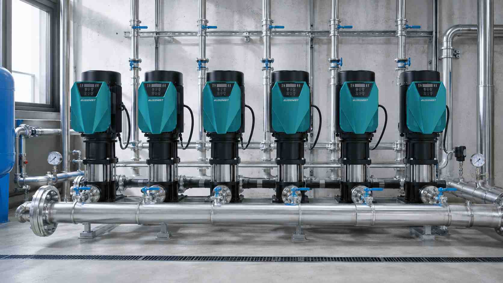
Engineering reference rendering; it is not a photograph of a commissioned customer system.
AUSENIST YS620 can be configured for a six-pump constant-pressure system using two main-control pumps and up to four auxiliary pumps. The architecture is intended for applications that need staged capacity, automatic rotation and continued control if one designated main drive becomes unavailable. Final communication topology and failover behavior must be verified during factory acceptance testing.
Reference Design at a Glance
| Item | Reference Requirement |
|---|---|
| Reference market | UAE commercial building |
| Pump quantity | Six equal or hydraulically compatible booster pumps |
| Architecture | Two main-capable pumps plus four auxiliary pumps |
| Drive series | AUSENIST YS620 |
| Feedback | Shared pressure transmitter, with project-specific redundancy if required |
| Communication | RS485 multi-pump link; external monitoring as designed |
| Functions | PID pressure control, staging, rotation, sleep and fault skip |
What Information Is Required?
- Nameplate and pump curve for every pump.
- Required pressure and minimum, normal and peak flow.
- Whether all pumps have equal capacity.
- Duty, assist and standby philosophy.
- Pressure-sensor range, mounting point and backup requirement.
- Required BMS/PLC points, alarms and communication protocol.
- Acceptance sequence for loss of a pump, sensor or controller.
Selection Example
For six identical 7.5kW, 380V pumps, use one correctly current-rated YS620 per motor. Two drives are assigned main-control capability and four act as auxiliary units. When flow demand rises beyond the lead pump’s capacity, the system starts additional pumps in stages. When demand falls, it removes pumps in a controlled order and allows the remaining running pump to regulate pressure.
This example does not fix the staging thresholds because they depend on the pump curves, pressure setpoint and system volume.
Recommended Control Logic
- The lead pump starts and regulates pressure through PID.
- If pressure remains below target while the lead pump is near its configured upper operating limit, an auxiliary pump is called.
- Pumps are added only after a confirmation delay to prevent rapid cycling.
- Pumps are removed as demand falls, using separate stop thresholds and delays.
- Timed rotation balances running hours.
- A failed auxiliary pump is skipped and the next available pump is called.
- The second main-capable controller takes over only according to the tested failover sequence.
Why This Configuration?
One VFD per pump provides independent soft starting, individual protection and better speed coordination. The two-main architecture reduces dependence on a single PID controller, while the auxiliary pumps provide staged capacity. It does not remove the need for correct hydraulic sizing, isolation valves, check valves and pressure-sensor design.
Expected Result and Acceptance Checks
Expected behavior includes stable pressure, orderly pump staging, balanced running hours and continued operation after a simulated pump fault. Factory or site testing should record lead-pump rotation, add/drop thresholds, communication loss, main-controller failover, dry-run response and recovery after a power interruption.
Common Mistakes
- Using six pumps without a written lead/lag/standby sequence.
- Setting identical start and stop thresholds, causing rapid cycling.
- Assuming controller redundancy also provides sensor redundancy.
- Mixing unequal pump curves without reviewing load sharing.
- Failing to test communication loss and fault skip before handover.
AUSENIST Solution
AUSENIST can provide YS620 model matching, multi-pump address planning, parameter pre-setting, wiring guidance and OEM documentation. If the project requires certified safety PLC functions, specialized fire-pump control or a site-specific statutory approval, those requirements must be reviewed separately.
FAQ
Does every pump need its own VFD?
For this reference architecture, yes. It gives each motor independent speed control and protection.
Can the six pumps have different power ratings?
It may be possible, but the hydraulic and control sequence must be engineered for unequal pumps.
What happens if one auxiliary pump trips?
The intended logic skips the unavailable pump and calls the next permitted unit, subject to correct commissioning.
Send us all six motor nameplates, pump curves, pressure target and control sequence. We can prepare the YS620 selection, address table and basic multi-pump parameters.