 Quanzhou Ausenist Technology Co., Ltd
 Two-Pump Constant Pressure System with Automatic Alternation
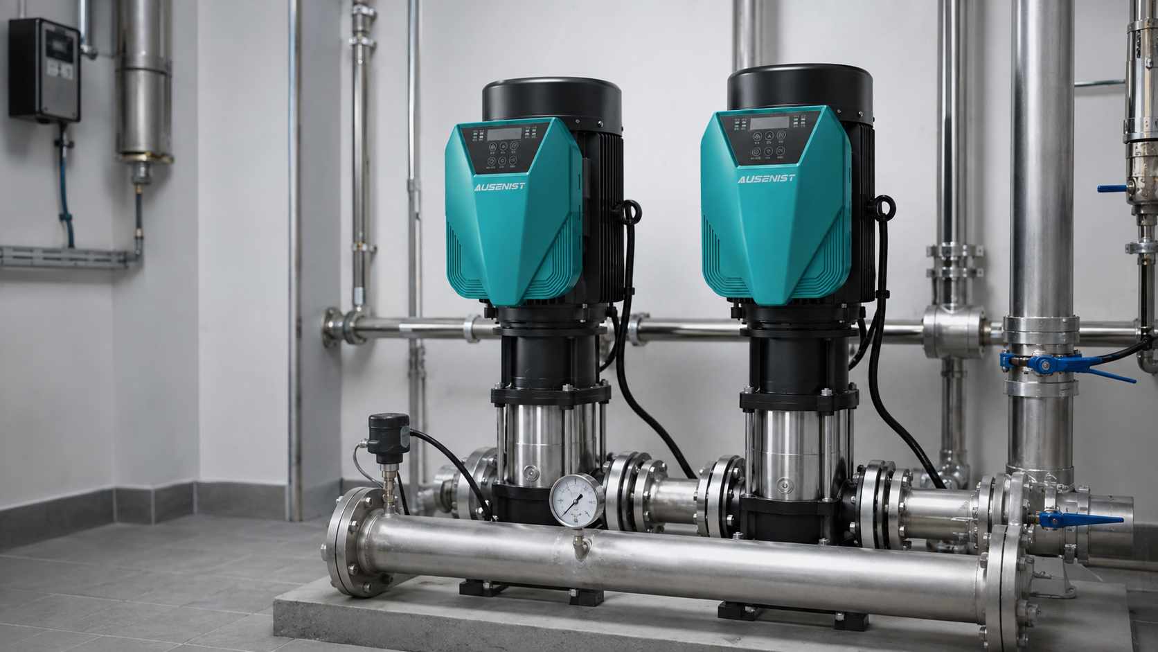
Engineering reference rendering; it is not a photograph of a commissioned customer system.
A two-pump constant-pressure system can use one correctly sized AUSENIST YS620 on each motor. One pump acts as lead and regulates pressure; the second starts when demand exceeds the lead pump’s capacity. Automatic alternation changes the lead assignment by time or completed cycle so operating hours remain more balanced.
Reference Design at a Glance
| Item | Reference Requirement |
|---|---|
| Reference market | Philippines |
| Pump set | Two 5.5kW vertical multistage booster pumps |
| Motors | 380V three-phase induction motors |
| Drives | Two AUSENIST YS620 units |
| Feedback | Common 4–20mA pressure transmitter |
| Functions | PID control, assist staging, alternation, sleep and fault skip |
What Information Is Required?
- Both motor nameplates and both pump curves.
- Target pressure and minimum, normal and peak flow.
- Whether either pump can meet the normal duty alone.
- Required alternation interval or rotation rule.
- Pressure transmitter range and installation point.
- Duty/assist/standby expectation after a fault.
- Power-recovery and BMS/PLC communication requirements.
Selection Example
For two identical 5.5kW, 380V pumps, select one YS620 per motor by rated current. The lead pump uses PID to maintain pressure. If it runs near the configured upper limit and pressure remains below target for a confirmation period, the assist pump starts. When demand falls, the assist pump stops after a separate delay and the lead pump continues regulating.
Recommended Control Logic
| Function | Initial Direction |
|---|---|
| Lead rotation | Alternate by accumulated time or completed cycle |
| Assist start | Pressure low plus lead pump near upper limit for a delay |
| Assist stop | Demand reduced for a separate, longer confirmation period |
| Sleep | Only when both demand and pressure behavior confirm no flow |
| Fault skip | Start the healthy pump and issue an alarm |
| Sensor failure | Use a predefined safe response and alarm |
Why This Configuration?
Two drives avoid hard starting the assist motor and allow both pumps to operate as lead units. Separate add and drop thresholds prevent rapid cycling. Automatic alternation balances usage but should not force a pump change during a critical transient.
Expected Result and Acceptance Checks
Expected behavior is stable pressure with one pump at normal demand, smooth addition of the second pump at peak demand and successful lead rotation. Test each pump as lead, assist start/stop, pressure-sensor failure, one-drive trip, sleep/wake and power recovery.
Common Mistakes
- Installing one VFD for two motors without a complete transfer and protection design.
- Using the same threshold for assist start and stop.
- Alternating pumps without checking that both deliver comparable flow.
- Relying on one pressure sensor without defining its failure response.
- Skipping check-valve and isolation-valve inspection.
AUSENIST Solution
AUSENIST can match both YS620 drives, prepare addresses and lead/lag parameters, support pressure feedback and provide OEM documentation for packaged booster sets. Fire-pump systems or installations governed by special safety codes require a separate compliant control design.
FAQ
Can one VFD control both pumps?
It is possible in some fixed-speed transfer arrangements, but two VFDs provide better independent control, protection and alternation for this design.
How often should the lead pump rotate?
The interval depends on operating hours, site maintenance policy and demand pattern. It should be verified during commissioning.
What happens if the lead drive trips?
The healthy unit should take over according to the commissioned fault-skip sequence and generate an alarm.
Send us both motor nameplates, pump curves, pressure target and duty sequence. We can prepare the YS620 selection and basic alternation parameters.