 Quanzhou Ausenist Technology Co., Ltd
 VFD for PMSM Water Pump Motor: Selection and Setup Guide
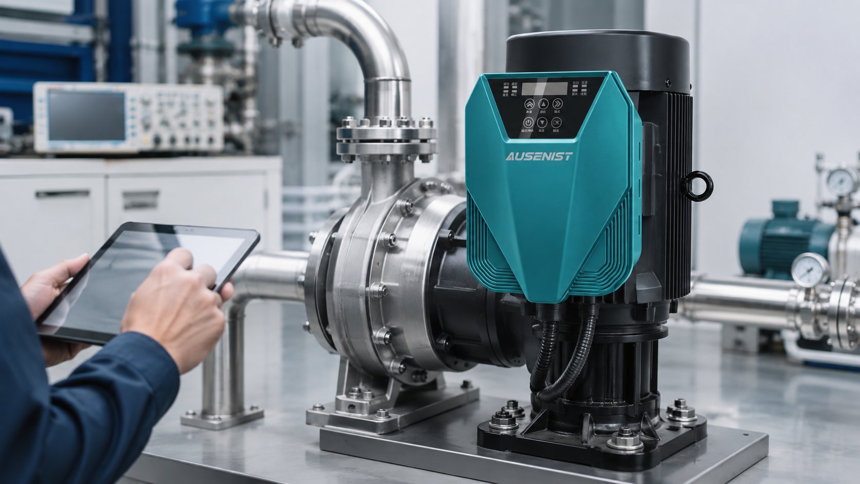
To select a VFD for a PMSM water-pump motor, confirm that the exact drive supports permanent-magnet synchronous motor control and that the required motor data can be entered or identified. Match the VFD by voltage and continuous output current, not kW alone. Correct motor parameters, direction, speed limits and pump protections must be validated before automatic pressure or flow control is enabled.
What Information Is Required?
- Complete PMSM nameplate: rated voltage, current, power, frequency, speed and pole information where stated.
- Motor supplier data required by the drive, such as resistance, inductance, back-EMF or flux-related values when available.
- Input voltage, phase, frequency and expected voltage variation.
- Pump type, curve, required flow and head, minimum safe speed and maximum permitted speed.
- Quantity of pumps and any lead, lag, alternation or standby requirements.
- Control target, sensor signal, start/stop source, communication and fault response.
- Whether static or rotating motor identification is permitted by the pump and site.
- Cable length, output filter, enclosure, temperature and altitude.
PMSM data formats differ between motor and VFD manufacturers. Do not guess a parameter or substitute an induction-motor setting with a similar name.
Selection Example
A PMSM centrifugal pump is marked 4 kW, 380 V, 7.8 A and 3,000 rpm. The proposed VFD must explicitly support the relevant PMSM control mode, provide a continuous output-current rating of at least 7.8 A after environmental derating, and accept the motor data needed for setup.
With the pump hydraulically prepared and the site safe, a qualified engineer enters the verified nameplate values and follows the exact manual for motor identification. If rotating identification is required, the pump must be allowed to rotate safely; valves, water supply and personnel protection must be considered. Direction and current are checked at low speed before the maximum speed, PID control and automatic restart are released.
Setup Sequence
- Confirm the VFD control mode supports the PMSM and the required feedback arrangement.
- Enter verified motor data using the units and definitions in the model-specific manual.
- Perform the permitted static or rotating identification procedure.
- Test direction, low-speed stability and motor current under safe hydraulic conditions.
- Set acceleration, deceleration, minimum and maximum speed within motor and pump limits.
- Add pressure, flow or level control and validate protection and restart behavior.
Common Mistakes
- Using a VFD that supports only induction motors.
- Matching by kW while ignoring PMSM current and control compatibility.
- Guessing motor parameters or copying values from a different PMSM.
- Running rotating identification on an unprepared or dry pump.
- Enabling automatic PID operation before direction and speed limits are verified.
AUSENIST Solution
AUSENIST can review PMSM nameplate data, available motor parameters, supply, pump curve and control requirements for a compatible YS620 or YS820 solution. Support may include drive selection, identification guidance, basic motor and pump parameters, constant-pressure logic and OEM validation planning.
Compatibility must be confirmed for the exact motor. AUSENIST should not promise stable PMSM control when essential motor data is unavailable, the drive lacks the required algorithm, the identification procedure cannot be performed safely, or the application exceeds confirmed ratings. Testing the actual motor and pump is the correct basis for an OEM release.
Send us your motor nameplate. We can recommend the VFD model and basic parameter configuration.