Application on Water Jet Loom
I. Basic Principles of Water Jet Loom
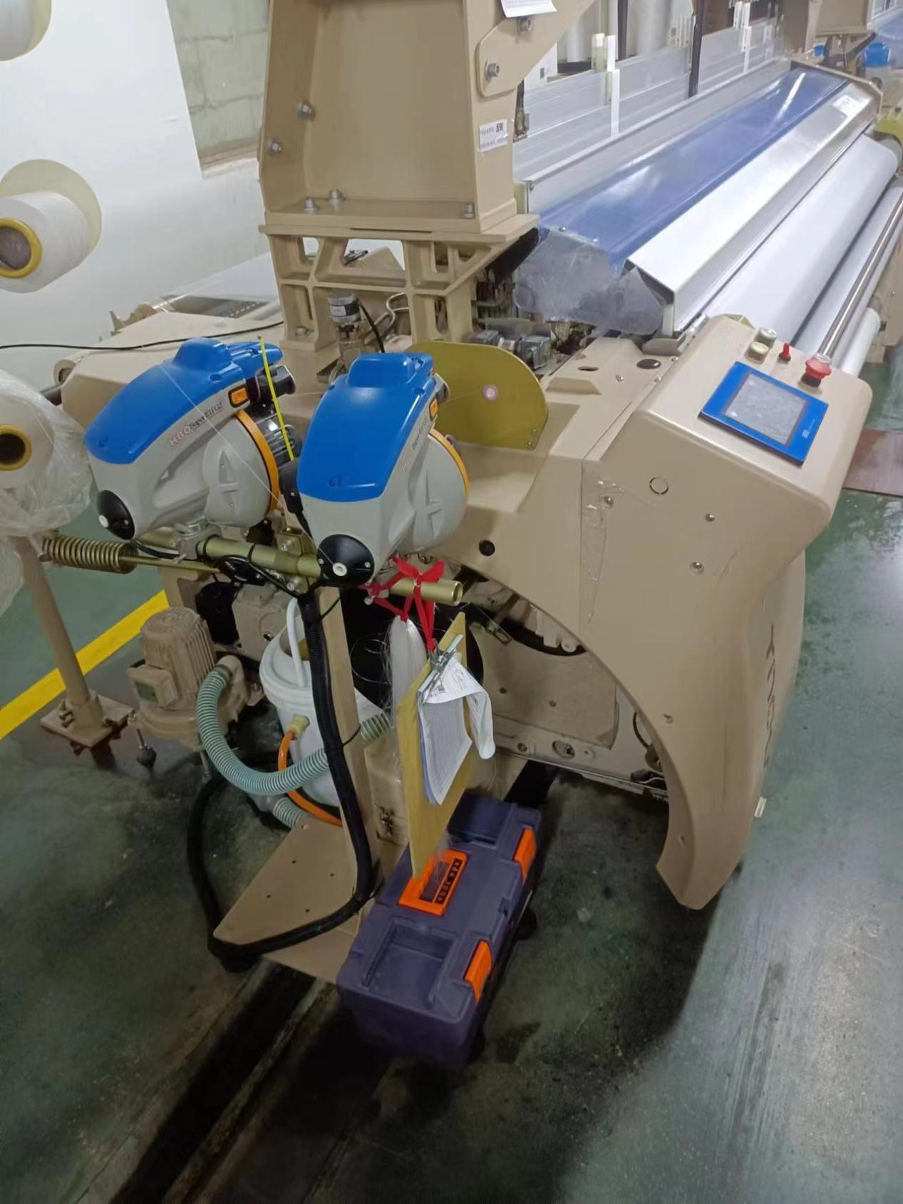
During the operation of the loom, the rotation of the water pump cam pulls the pump cam rod to move to the left, causing the water pump to draw water from the float box. The presser opens simultaneously, releasing the weft yarn. The water flow carries the weft yarn from one side of the fabric to the other. After the weft insertion is complete, the presser closes, holding the weft yarn until the next insertion.
II. Maintenance of Water Jet Loom
When the loom stops, step on the weft insertion pedal, push the pump cam rod, pull the water pump plunger, draw water from the float box, release the pedal, and water will be sprayed from the nozzle, completing one weft insertion.
To maintain the water jet loom, ensure the following elements at the moment of entering the light carbon before the flight ends:
Adjust the encoder angle, which has specific requirements for start-up and stop angles.
Ensure clear shedding of the heddle, with no major bends.
The thread ear silk on the nozzle side should be below 280°, and the downstroke should be at 20° to ensure that the planetary gear has no kinetic energy.
The downstroke scissors should have no scratches and should not cut the thread.
The middle frame should have no momentum, and the rod sheath for the pulling rod should have no wear.
Ensure smooth operation of the tail system without scraping.
III. Our Inverter Controls the Inner Rotor Motor for Super Start
The water jet loom uses a permanent magnet inner rotor motor, which requires super start, fast start, fast stop, and specific stop position angles. This is why it is necessary to correct the zero position of the encoder during equipment maintenance. If the stop angle is incorrect, it can lead to severe thread breakage, and the produced products may not meet quality requirements.
IV. Inverter Wiring Control Diagram and Debugging for Water Jet Loom
In coordination with the water jet loom system, the inverter uses 485 communication and connects to terminals X1 to X4 with the common point COM.
Terminal Connection:
X1: Forward
X2: Forward point 3
X3: Reverse
X4: Brake
COM: Common point
Debugging Steps:
Identify the inner rotor motor and confirm the correct direction.
Set communication parameters and inverter terminal functions.
Adjust acceleration and deceleration times in coordination with the water jet loom system.
The equipment must be equipped with a braking resistor.
V. Equipment Product Images
 Quanzhou Ausenist Technology Co., Ltd

