 Quanzhou Ausenist Technology Co., Ltd
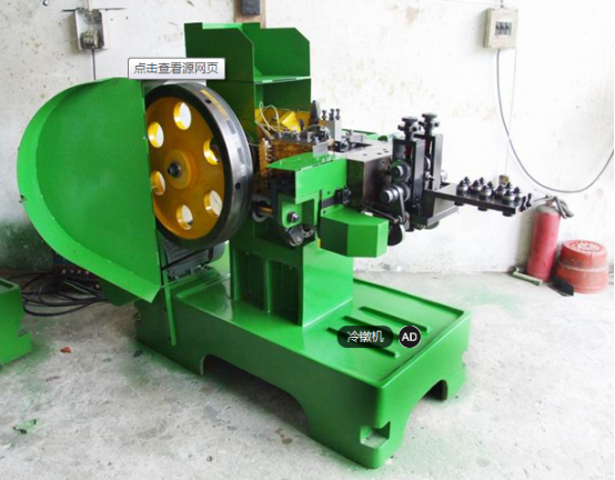
 Cold heading is a process that involves placing a blank in the mold of an automatic cold heading machine at room temperature, applying pressure to the mold, and using the relative movement of the upper and lower dies to deform and greatly reduce the height of the blank while increasing the cross-sectional area. In actual production, the cold forming process for fasteners often involves extrusion during cold heading. Therefore, in terms of the cold heading process for fastener products, it is essentially a composite processing method that includes both cold heading and extrusion. The cold heading machine is a specialized device designed primarily for the mass production of fasteners such as nuts and bolts. The world's earliest cold heading machines originated in Germany, where the main purpose of developing cold heading machines was to mass-produce bullet casings during World War II.
I. Drawbacks of Traditional Cold Heading Machines
Standard Part Production: The size, length, and material of equipment-produced standard parts depend on changing the flywheel size to adjust the feed speed of the rollers. Therefore, for each change in production parts or materials, the large flywheel must be removed and a suitable flywheel installed, resulting in significant waste of labor, resources, and time.
Control Disadvantages: In normal operation, the forward and reverse jog and startup currents are about three times higher than normal (resulting in significant power wastage). Contactors are prone to damage, motor speed cannot be adjusted, which does not meet the process requirements of the product, and has a significant impact on the power grid and mechanical equipment, leading to high maintenance costs and production disruption.
Advantages of Variable Frequency Conversion
Variable frequency control allows for stepless motor speed control. Changing the frequency achieves the required speed without the need to replace the flywheel. The debugging process is more convenient, accurate, and fully secure.
Ensures uniform load increase and decrease, keeping the machinery in a smoother load fluctuation to prevent large fluctuations in motor and working device actions, thus extending the service life.
Possesses excellent overcurrent protection capabilities. In the case of equipment jamming or insufficient lubrication oil leading to motor overload, proper overcurrent protection settings on the variable frequency inverter can effectively protect the motor, preventing overload damage.
Improves power factor and energy efficiency. The effect is less pronounced for small motors, but for larger motors, the improvement is significant.
II. Electrical Wiring Diagrams
Main Circuit Wiring Diagram
Control Circuit Wiring Diagram
III. Parameter Adjustment Instructions
Parameter Settings
F0.02: 1 — Terminal control
F0.03: 2 — Main frequency given external potentiometer
F0.17, F0.18 — Acceleration and deceleration time
F2.00-F2.03 — Input terminal function settings: Forward operation - 1, Jog forward - 4, Fault reset - 9
Debugging Process Explanation
After the peripheral devices are connected and checked for accuracy, conduct a no-load power-on test first to familiarize yourself with the protection codes in case of inverter operation failure. Familiarize yourself with the key operation and modify the required parameters according to the manual.
Loaded Operation: Set the inverter to keyboard operation mode, press the run and stop keys, and observe whether the motor can start and stop normally and whether the keyboard display is normal.
If the motor cannot start, try the motor self-learning function.
If the inverter triggers overcurrent protection, re-set the acceleration and deceleration times.
If the protection persists within the specified time, change the run-stop operation curve.
If the inverter still has a fault, consider increasing the current protection value, but do not eliminate it. Leave at least 10%-20% protection margin.
If the fault still occurs, consider replacing the inverter with a higher power level.
If the motor does not reach the preset speed, consider two situations:
Mechanical and electrical resonance may occur in the system, which can be judged by the sound of the motor operation. Using the frequency jump value setting can avoid resonance points.
The torque output capability of the motor may be insufficient. Manually increase the torque boost value, avoiding setting it too high. Alternatively, a new control method, such as sensorless vector control, can be adopted for greater torque output.
If the equipment on-site cannot be used normally or if the inverter triggers a fault alarm, please contact the after-sales engineer for consultation and resolution.
IV. Related Precautions
Ensure that the power is completely cut off for at least 10 minutes before opening the inverter cover.
Confirm that the voltage value between terminals P+ and P- of the main circuit is below 36VDC before performing internal wiring operations.
Verify that the rated input voltage of the inverter is consistent with the voltage of the AC power supply. If the input voltage levels are inconsistent, it may lead to inverter damage.
Install in sequence, i.e., install the main body first and then connect the wires to prevent electrical accidents or damage to the inverter.
The inverter has undergone a withstand voltage test before leaving the factory. Users should not conduct a withstand voltage test on the inverter again.
Ensure that the grounding terminal of the inverter is connected to the motor housing and the grounding wire. A copper-core wire with a cross-sectional area of 4cm2 or more should be used, and the ground resistance must be less than 10Ω.
It is strictly forbidden to connect terminals A, B, C other than the control terminals to AC 220V power, as this may damage the inverter.
It is strictly forbidden to connect AC power to the output terminals U, V, W of the inverter, as this will cause damage to the inverter.